 Tiếng Việt
 English
 中文
 Español
 हिन्दी
 Français
 Português
 Русский
 Deutsch
 日本語
 한국어
 Italiano
 Bahasa Indonesia
 ไทย
 বাংলা
 ລາວ
 မြန်မာ
 العربية
 فارسی
 اردو
 Українська
 Română
 Azərbaycan
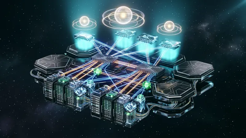
Modern hyperscale cloud data centers and high-availability edge VPN fabrics demand non-blocking throughput and sub-second failure recovery. Historically, network operators relied on multi-chassis link aggregation (MLAG) or vendor stacking to connect dual-homed customer devices to redundant top-of-rack leaf switches.
However, MLAG couples chassis control planes across proprietary inter-switch links (ISL), introducing configuration drift, split-brain failure modes, and rigid scaling limits. The Internet Engineering Task Force (IETF) solved these architectural challenges by standardizing Ethernet Virtual Private Network (EVPN) multi-homing in RFC 7432 and RFC 8365.
By decoupling link redundancy from physical peer-switch interconnections, EVPN establishes an open, standards-compliant control plane using Multiprotocol BGP (MP-BGP). Through Ethernet Segment Identifiers (ESI), all-active forwarding, Designated Forwarder (DF) election, and symmetric anycast gateways, EVPN delivers resilient active-active forwarding across modern cloud infrastructures.
The Legacy MLAG Dead End: Why Proprietary Layer 2 Redundancy Fails at Scale
For decades, multi-chassis link aggregation provided host dual-homing without Spanning Tree Protocol (STP) blocking redundant links. MLAG pairs two physical switches together to present a unified IEEE 802.1AX LACP bundle to an attached server or router.
Despite widespread use, MLAG exhibits critical structural flaws:
- Proprietary Control Plane Coupling: MLAG requires vendor-specific heartbeats across an inter-switch link (ISL). Operators cannot pair hardware from different switch manufacturers in the same redundancy group.
- Split-Brain Risks: When the peer-link fails and heartbeat signals drop, both switches assume active ownership of the shared virtual IP and MAC. This condition generates duplicate packets and corrupts ARP tables.
- Rigid Two-Chassis Limit: MLAG topologies cannot scale beyond two leaf chassis, preventing multi-homing across three or four leaf switches in separate availability rows.
EVPN replaces this model by moving multi-chassis coordination directly into standard MP-BGP signaling.
Architecture of BGP EVPN Multi-Homing: The RFC 7432 Control Plane
RFC 7432 defines EVPN as a BGP-based control plane for Ethernet services across IP and MPLS fabrics. In an EVPN multi-homing topology, redundant leaf switches operate completely independent control planes without dedicated peer-links.
Coordination occurs via standard MP-BGP AFI 25 (L2VPN) and SAFI 70 (EVPN) route announcements across the IP underlay.
Ethernet Segment Identifiers (ESI): Decoupling Links from Physical Hardware
An Ethernet Segment (ES) represents the redundant physical links connecting a multi-homed customer device to multiple leaf switches (Provider Edge or PE nodes). Every segment is identified by a unique 10-octet Ethernet Segment Identifier (ESI).
RFC 7432 standardizes several ESI types. In data center overlays, Type 0 (manual configuration) and Type 1 (auto-generated from IEEE 802.1AX LACP system ID and port key) are standard:
+-------------------+---------------------------------------+
| ESI Type (1 byte) | Value (9 bytes)                       |
+-------------------+---------------------------------------+
| Type 0x00         | Arbitrary 9-octet manual identifier   |
| Type 0x01         | CE MAC Address (6B) + Port Key (2B)+0 |
+-------------------+---------------------------------------+
When independent leaf switches share the same non-zero ESI on downstream interfaces, they recognize that they connect to the same physical Ethernet Segment and initiate multi-homing synchronization.
EVPN Route Types in Action: Auto-Discovery and Ethernet Segment Signatures
RFC 7432 defines dedicated BGP Network Layer Reachability Information (NLRI) route types for multi-homing:
- Route Type 1 (Ethernet Auto-Discovery Route): Advertised per-ESI to announce all-active capabilities and distribute split-horizon filtering labels. It also drives sub-second mass withdrawal during link faults.
- Route Type 2 (MAC/IP Advertisement Route): Advertises host MAC addresses and optional ARP bindings learned on an ESI, associated with route targets and Layer 2 VNIs.
- Route Type 4 (Ethernet Segment Route): Discovers peer leaf switches attached to the identical ESI, exchanging IP addresses to initiate Designated Forwarder elections.
All-Active Forwarding: Achieving Symmetrical Multi-Chassis Load Balancing
EVPN supports two redundancy modes: Single-Active and All-Active. In Single-Active mode, only one designated switch forwards traffic while backup links remain standby. In All-Active mode, all connected leaf switches concurrently forward unicast frames to and from the customer edge device.
Because the customer device configures a standard LACP trunk across all physical links, outgoing traffic balances across all connected leaf switches. The switches encapsulate and route this traffic across the VXLAN underlay without creating forwarding loops.
The Loop Prevention Architecture: Split-Horizon Filtering via ESI Labels
In an all-active topology, when a host sends a broadcast, unknown unicast, or multicast (BUM) packet to Leaf-1, Leaf-1 replicates the frame across the VXLAN fabric to Leaf-2. However, Leaf-2 also connects directly to the originating customer device over the shared ESI.
If Leaf-2 forwarded this replicated packet back down to the server, a Layer 2 loop would occur. EVPN prevents this through split-horizon filtering:
- Leaf switches advertise an ESI Label in their Ethernet Auto-Discovery routes (Route Type 1 per-ES).
- When Leaf-1 encapsulates a BUM packet from ESI-A into VXLAN, it adds an ESI tunnel label or source identifier.
- Upon receiving the encapsulated packet from the core fabric, Leaf-2 inspects the source ESI label. If the packet originated from ESI-A, Leaf-2 drops the frame on its local ESI-A interface while forwarding it to all other local interfaces.
This hardware-level filtering suppresses frame echo without disabling physical links.
Designated Forwarder (DF) Election: Suppressing Duplicate BUM Flooding
While all-active multi-homing permits every connected leaf switch to forward known unicast traffic, multi-destination BUM traffic must be handled by exactly one switch per broadcast domain. If multiple leaf switches forwarded core-originated broadcast traffic down to the server, duplicate packets would flood the segment.
EVPN introduces Designated Forwarder (DF) election to assign a single active forwarder for BUM traffic per VLAN or Ethernet Tag.
The Modulo Election Algorithm: Mechanics and Uneven Hashing Caveats
RFC 7432 specifies a default modulo-based DF election algorithm. Leaf switches collect Route Type 4 announcements for a target ESI, create an ordered list of candidate IP addresses, and assign an index i (from 0 to N - 1).
The leaf elected as Designated Forwarder for VLAN V is computed as:
DF Index = V mod N
Where V is the VLAN ID and N is the count of candidate PE switches. While straightforward, modulo election suffers from hashing skew when VLAN ranges are sparse, leading to uneven load distribution.
Preference-Based DF Election: Deterministic Control via RFC 8584
To resolve modulo limitations, RFC 8584 establishes an extensible DF election framework. It introduces preference-based DF election using a dedicated BGP DF Election Extended Community:
+-----------------------------------------------------------+
| DF Preference (2 bytes) | DF Election Flags (2 bytes)     |
+-----------------------------------------------------------+
Engineers assign explicit preference values (0 to 65535) per leaf switch. The leaf with the highest preference becomes the primary DF. RFC 8584 also supports graceful preemption timers and "Don't Preempt Me" (DP) bits, preventing packet flapping when a rebooted switch rejoins an active Ethernet Segment.
Distributed Anycast Gateways: Symmetric IRB Routing Across Leaf Switches
EVPN multi-homing integrates with Integrated Routing and Bridging (IRB) to route traffic between subnets. Traditional first-hop redundancy protocols (FHRP) like VRRP funnel default gateway traffic through an active router.
In contrast, EVPN deploys a Distributed Anycast Gateway across all leaf switches:
- Every leaf switch configures an identical virtual IP and virtual MAC for the default gateway of each subnet (e.g., IP
10.100.1.1/24, MAC00:00:5E:00:01:01). - When a host issues an ARP request for its default gateway, the local leaf switch resolves the request directly.
- Inter-subnet routing occurs locally on the first-hop leaf switch using Symmetric IRB (RFC 9135). Packets traverse the spine fabric encapsulated in a Layer 3 VNI (such as VNI 50000), eliminating hairpinned transit paths through central core routers.
Fast Convergence and Mass Withdraw: Eliminating MAC Blackholing on Link Outages
In large data centers, an Ethernet Segment may host tens of thousands of MAC addresses. If a link between Leaf-1 and a dual-homed server fails, withdrawing every individual Route Type 2 (MAC advertisement) via BGP takes several seconds, causing packet loss.
EVPN solves this through Aliasing and Mass Withdrawal:
Host MAC (00:1A:2B:3C:4D:5E) ---> Advertised with ESI-123 (Route Type 2)
Leaf-1 and Leaf-2            ---> Advertise ESI-123 Reachability (Route Type 1)
Remote leaf switches configure equal-cost multi-path (ECMP) forwarding entries toward both Leaf-1 and Leaf-2 for MACs associated with ESI-123. When Leaf-1 detects a local link failure:
- Leaf-1 immediately withdraws only its single Route Type 1 route for ESI-123.
- Remote switches instantly remove Leaf-1 from their ECMP next-hop list for all MAC addresses linked to ESI-123, redirecting traffic to Leaf-2 within milliseconds.
- Leaf-1 cleans up its individual Route Type 2 advertisements in the background without dropping active flows.
To inspect transit routing behaviors and evaluate egress paths, operators can analyze hop-by-hop forwarding through our IP inspection tool.
RiceGuard Edge Fabric: Resilient Anycast Gateway Infrastructure
At VPNRice, the RiceGuard high-availability backbone deploys RFC 7432 BGP EVPN all-active multi-homing across its multi-region edge points of presence. By eliminating proprietary MLAG clusters, our infrastructure delivers carrier-grade resilience:
- Hitless Edge Maintenance: Edge gateway nodes undergo kernel updates seamlessly. RFC 8584 preference manipulation allows graceful traffic draining to sister nodes before maintenance begins.
- Symmetric ECMP Ingress: Traffic arriving from diverse transit providers balances across all-active compute clusters, preventing asymmetric routing bottlenecks. Users downloading secure client builds through our client software experience uninterrupted multi-path throughput.
- Telemetry-Guided Underlay Routing: Layer 2 and Layer 3 overlay states integrate directly with real-time transit telemetry, building on principles explored in our deep dives on SRv6 network programming and GRE-in-UDP and GENEVE ECMP hashing.
Practical Implementation: Configuring EVPN Multi-Homing in Linux FRRouting
Open-source network stacks like FRRouting (FRR) support RFC 7432 EVPN multi-homing in Linux environments. Below is a configuration for an all-active Ethernet Segment and Anycast Gateway in FRRouting:
! /etc/frr/frr.conf
router bgp 65001
 bgp router-id 192.0.2.11
 no bgp default ipv4-unicast
 neighbor FABRIC peer-group
 neighbor FABRIC remote-as 65000
 neighbor 192.0.2.1 peer-group FABRIC
 !
 address-family l2vpn evpn
  neighbor FABRIC activate
  advertise-all-vni
  advertise-default-gw
  autort rfc8365-compatible
 exit-address-family
!
interface bond0
 description Dual-Homed CE Link
 evpn multihoming es-id 00:11:22:33:44:55:66:77:88:99
 evpn multihoming es-sys-mac 00:11:22:33:44:55
 evpn multihoming df-preference 50000
!
interface vlan100
 description Anycast Gateway Subnet
 ip address 10.100.1.1/24
 ip gateway-address 10.100.1.1
By transitioning network fabrics from fragile proprietary MLAG clusters to standard BGP EVPN all-active multi-homing, infrastructure teams achieve deterministic fault isolation, open multi-vendor interoperability, and horizontal scalability.